
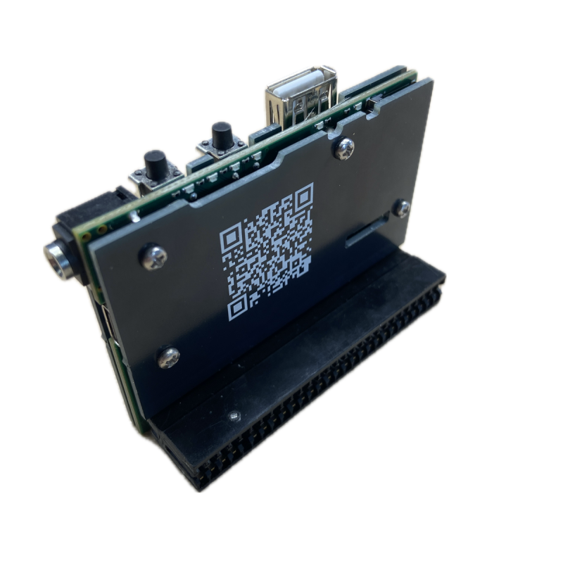
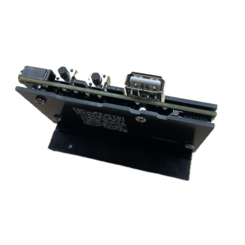
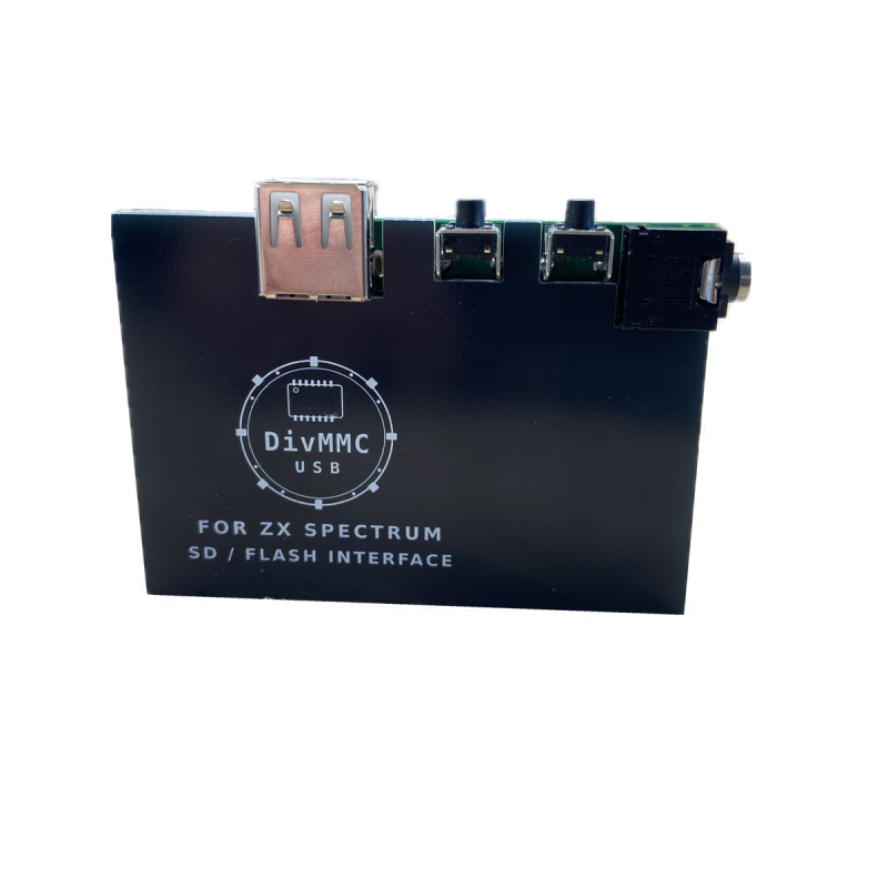
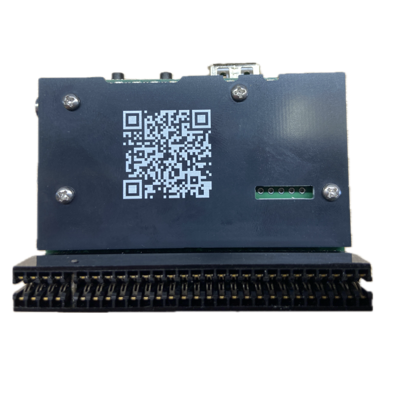


The ultimate multidevice for ZX Spectrum (DivMMC, dual AY-3-8912 emulation, mouse / joystick interface)

Delivery information

Returns policy

Warranty information
DivMMC USB is the ultimate multidevice for the Sinclair ZX Spectrum computers
Based on FPGA/ARM - designed, studied, and built over many months of research
To the best of our knowledge, this is the only device of its kind in the world. Every single feature described below was the result of months of studying original ZX Spectrum hardware documentation, protocol specifications, USB HID reports, FPGA timing constraints, and countless hours of trial-and-error debugging with logic analysers, oscilloscopes, and a healthy dose of stubbornness. Nothing here was trivial. Nothing here was handed on a plate.
1. DivMMC
Full DivMMC compatible SD card interface, directly accessible from theZ80 bus. Supports standard DivMMC firmware and SD card images.
2. ROM Switcher
Up to 4 selectable 16 KB ROM slots. Switch between different ROM images without physically swapping chips. Selection is done through the built-in BIOS/GUI configuration menu. ROM switcher is more like CART runner, that utilises rom files of 16kb. After reset, FPGA sets path and ROM image is copied to SRAM from SPI flash and mapped in the place of original ROM (first 16k).
3. GameCart
Up to 4 MB of flash storage for Z80 and SNA snapshot files. Games are flashed to the onboard SPI flash via SD card. The FPGA handles the complete boot sequence: reading the flash, loading the snapshot into RAM, and releasing the Z80 to run.
4. USB Host - supports joysticks / mice / keyboards
A dedicated ATSAMD21 microcontroller operates as a USB Host, accepting standard USB joysticks, gamepads, keyboards and mice - including wireless devices with USB dongles. The MCU parses HID report descriptors at a runtime, meaning it adapts to virtually any USB HID device without hardcoded assumptions. Device type is automatically detected and signaled to the FPGA. Communication between the SAMD21 and the FPGA uses a custom 15-byte SPI protocol at 4MHz, carrying button states, movement deltas, keys pressed and scroll data in real time. The system detects when a USB device is connected or disconnected and signals this to the FPGA. The FPGA can then adjust its behaviour accordingly - for example, switching between joystick emulation modes and Kempston mouse mode.
5. Dual AY-3-8912 Sound (TurboSound)
Two emulated AY-3-8912 sound chips, providing full TurboSound compatibility. Active AY chip is selected via standard I/O port protocol. Stereo output with configurable channel mapping (ABC/ACB). Additionally supports Covox and Soundrive interfaces.
6. BIOS / GUI Configuration
All device settings - joystick mode, ROM slot, sound options, DivMMC vs GameCart mode - are configured through a built-in on-screen menu. Settings are stored in SPI flash and persist across power cycles.
7. USB-C FPGA Programmer
A USB-C connector is provided for reflashing the FPGA bitstream, enabling future firmware upgrades without any special hardware.
The Kempston mouse interface uses three I/O ports. Button bits are active low, meaning a pressed button reads as 0. The counters are free-running 8-bit accumulators that wrap around from 255 to 0 and vice versa. Software reads them periodically and calculates the difference since the last read to determine movement direction and speed.
Port FADF hex (64223 decimal) — 3 Buttons and Scroll
Bit 0 Right mouse button (0 = pressed, 1 = released)
Bit 1 Left mouse button (0 = pressed, 1 = released)
Bit 2 Middle mouse button (0 = pressed, 1 = released)
Bit 3 Always 1
Bit 4 Scroll wheel counter, bit 0
Bit 5 Scroll wheel counter, bit 1
Bit 6 Scroll wheel counter, bit 2
Bit 7 Scroll wheel counter, bit 3
The scroll wheel counter is a 4-bit accumulator. It increments when the wheel is scrolled up and decrements when scrolled down.
Port FBDF hex (64479 decimal) — X Position Counter
Bits 0–7 8-bit X counter
Increases when the mouse moves right. Decreases when the mouse moves left.
Port FFDF hex (65503 decimal) — Y Position Counter
Bits 0–7 8-bit Y counter
Increases when the mouse moves up. Decreases when the mouse moves down.
The device supports seven distinct joystick emulation modes, covering every major standard used by ZX Spectrum software. Each mode is selectable through the BIOS menu. The SAMD21 microcontroller translates USB HID gamepad reports into a universal button byte, and the FPGA maps this byte onto the correct I/O port(s) and bit layout for the selected mode.
Mode 0 - Kempston
I/O port: 31 decimal (0x1F)
Accent: Active HIGH (1 = pressed, 0 = released)
Bit 0 Right
Bit 1 Left
Bit 2 Down
Bit 3 Up
Bit 4 Fire 1
Bit 5 Fire 2
Bit 6 Fire 3 (for gamepad)
Bit 7 Fire 4 (for gamepad)
This is most common standard for joystick interfaces on the ZX Spectrum. Directly readable without conflicting with the keyboard matrix.
Mode 1 - Sinclair 1
I/O port: 0xF7FE
Accent: Active LOW (0 = pressed, 1 = released)
Emulates: Keyboard half-row 6, 7, 8, 9, 0
Bit 0 Fire (key 6)
Bit 1 Up (key 7)
Bit 2 Down (key 8)
Bit 3 Right (key 9)
Bit 4 Left (key 0)
Designed for use with Sinclair joystick port 1 (right-hand side). Maps directly onto keyboard scan lines, so software that reads the keyboard will see joystick input without any special driver.
Mode 2 - Sinclair 2
I/O port: 0xEFFE
Accent: Active LOW (0 = pressed, 1 = released)
Emulates: Keyboard half-row 1, 2, 3, 4, 5
Bit 0 Fire (key 5)
Bit 1 Up (key 4)
Bit 2 Down (key 3)
Bit 3 Right (key 2)
Bit 4 Left (key 1)
The mirror of Sinclair 1, intended for the left-hand side joystick port. Used by many two-player games and some single-player titles.
Mode 3 - Protek
I/O ports: 0xEFFE and 0xF7FE
Accent: Active LOW (0 = pressed, 1 = released)
Port 0xEFFE:
Bit 0 Fire
Bit 2 Right
Bit 3 Down
Bit 4 Up
Port 0xF7FE:
Bit 4 Left
The Protek interface splits direction and fire signals across two keyboard half-rows. A somewhat uncommon interface, but required for full compatibility with certain titles from the mid-1980s.
Mode 4 - Fuller
I/O port: 127 decimal (0x7F)
Accent: Mixed polarity (Fuller-specific active levels)
Bit 0 Up
Bit 1 Down
Bit 2 Left
Bit 3 Right
Bit 5 Fire 2
Bit 7 Fire 1
The Fuller joystick interface was part of the Fuller Box, which also included a sound chip. It uses its own unique port and bit layout that does not match any other standard.
Mode 5 - QAOP SPACE
I/O ports: 0xFBFE, 0xFDFE, 0xDFFE, 0x7FFE
Accent: Active LOW (0 = pressed, 1 = released)
Emulates: Keyboard keys Q, A, O, P, SPACE
Port 0xFBFE: Bit 0 = Up (key Q)
Port 0xFDFE: Bit 0 = Down (key A)
Port 0xDFFE: Bit 0 = Right (key P)
Bit 1 = Left (key O)
Port 0x7FFE: Bit 0 = Fire (key SPACE)
The most common keyboard control scheme in ZX Spectrum games. QAOP+SPACE was the default layout for a huge number of titles. This mode injects keypresses directly into the keyboard matrix, making it compatible with virtually any game that supports redefinable keys.
Mode 6 - QAOP M
I/O ports: 0xFBFE, 0xFDFE, 0xDFFE, 0x7FFE
Accent: Active LOW (0 = pressed, 1 = released)
Emulates: Keyboard keys Q, A, O, P, M
Identical to QAOP SPACE, except the fire button is mapped to the M key instead of SPACE:
Port 0x7FFE: Bit 2 = Fire (key M)
Some games used M as the primary action key. This mode provides that mapping without requiring software key redefinition.
The ultimate multidevice for ZX Spectrum (DivMMC, dual AY-3-8912 emulation, mouse / joystick interface)