
GTIA2RGB
search
  • GTIA2RGB
  • GTIA2RGB
  • GTIA2RGB
  • GTIA2RGB
  • GTIA2RGB
  • GTIA2RGB
GTIA2RGB
GTIA2RGB GTIA2RGB GTIA2RGB GTIA2RGB GTIA2RGB GTIA2RGB

GTIA2RGB

£67.00
VAT included Free delivery

Adapter for Atari 8-bit providing RGB output and new graphics modes 

Quantity
In stock


Delivery information


Returns policy


Warranty information

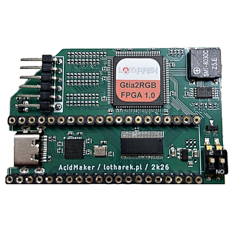
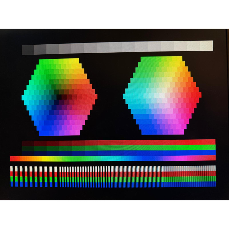
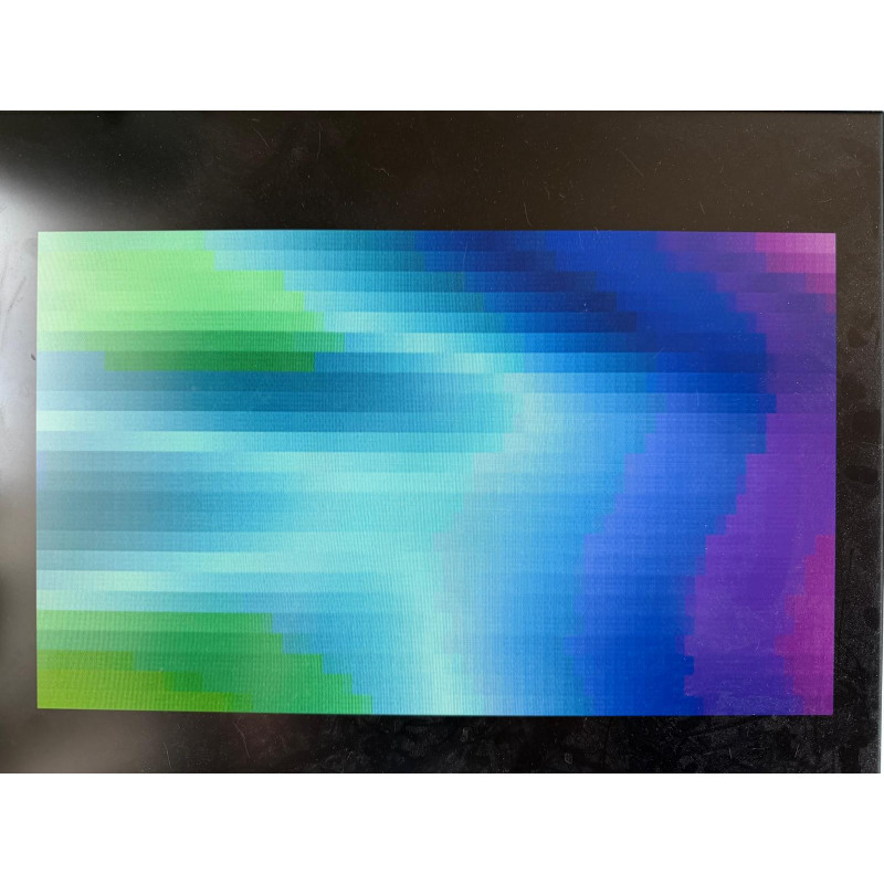
This is a FPGA based adapter for Atari 8-bit computer adding new graphics modes and crystal clear RGB output in 2 modes. It is fitted between original GTIA chip and Atari motherboard.

RGB output works in one of two modes:

  • RGB 15kHz (Amiga / VBXE style)
  • VGA 31 kHz (VGA)

Features

  • On Screen Display (press and hold for about 2 seconds Start + Select + Option on Atari keyboard to enter OSD settings)
  • Config stored in EEPROM
  • Buzzer (extra feature)
  • DIP switches to select output mode
  • 2k4 luts FPGA Gw1N
  • 24bit DAC
  • FPGA firmware can be flashed via USB-C
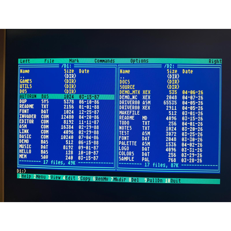
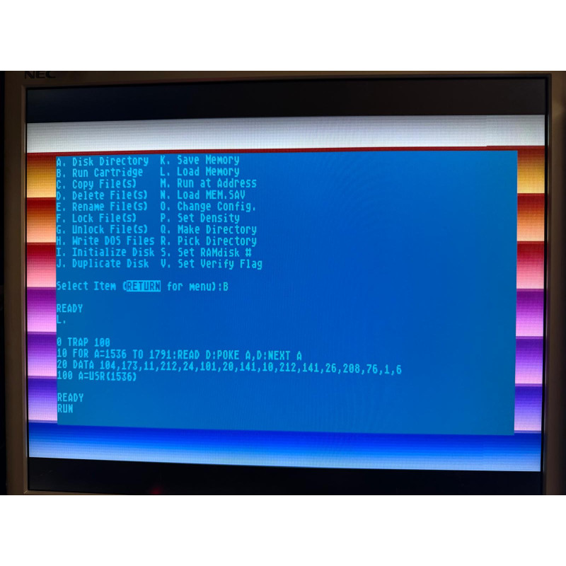
  • 80 columns mode - please refer to manual in the Downloads section above

Installation manual (work in progress)

Prior to installation, please upgrade firmware to most present version. Devices are sent with initial firmware.
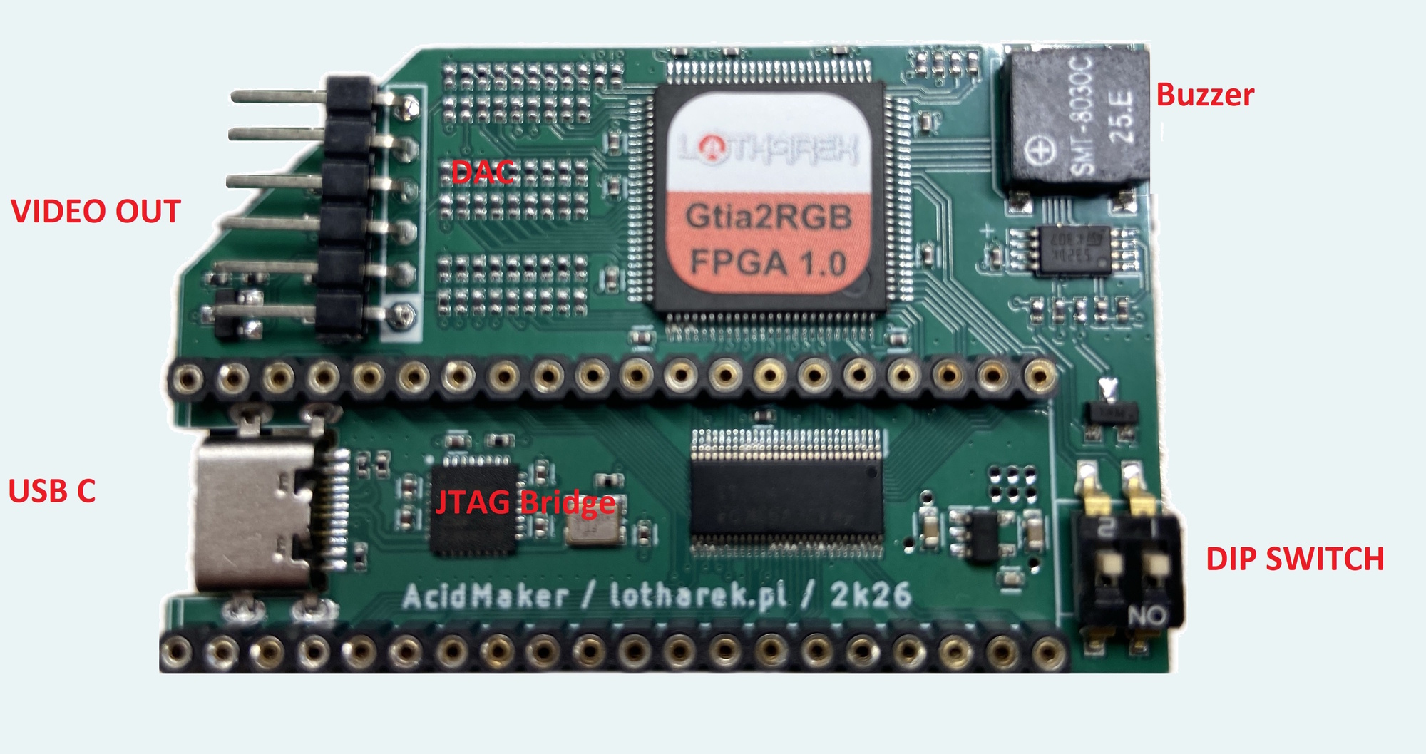
GTIA2RGB description

Step by step

  • If your GTIA is soldered into the motherboard, desolder GTIA, solder back GTIA2RGB and then insert GTIA into it. Please make sure pin one of both adapter and chip are correctly aligned.
  • If your GTIA is in the socket, remove GTIA from it, remove carefully GTIA2RGB's bottom socket (to decrease it's height), insert device into the socket on Atari motherboard and put GTIA back. Please make sure pin one of both adapter and chip are correctly aligned.
  • Start computer as usually. Press few keys. If you hear beeps/clicks from embedded speaker and Atari works, you have successfully made hardware installation.
  • Update FPGA firmware
    • Download latest firmware and save it to the disk.
    • Connect USB-C cable from GTIA2RGB and to PC.
    • Power on Atari.
    • In Device Manager in Windows new device will be detected.
    • Follow manual in order to install drivers and download software (available in the Downloads tab above). FPGA type to be used is GW1N-2B.
  • Select RGB output mode (refer to installation manual for DIP switch function description):

31 kHz (VGA monitor) connection diagram

SIGNAL GTIA2RGB
(pin 1 is marked with
white square on the PCB)
VGA
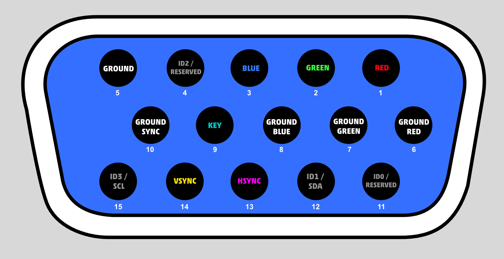
VGA Connector pin out
GND pin 1 at least one of these pins
(suggested to connect all):
5,6,7,8,10
(no pin 9!)
RED pin 2 1
GREEN pin 3 2
BLUE pin 4 3
HSYNC pin 5 13
VSYNC pin 6 14

15 kHz (SCART, RGB monitor) connection diagram

...any moment now...

Credits

Design/Production - Lotharek
Software / craziest ideas - AcidMaker

GTIA2RGB

You might also like